What Is a Precision Gear Motor and How Does It Work?

Time:2026-10-28 Author:Amelia
0%

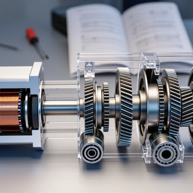
A Precision Gear Motor combines a compact electric motor with a gear train that controls speed, torque, and movement. It appears in robotic joints, medical instruments, camera systems, laboratory equipment, and automated production lines. The motor creates rotation. The gears refine it.

Gear authority Darle W. Dudley offered a practical view: “Gears transmit motion and power between shafts.” That simple statement explains the motor’s central purpose. A small motor may spin quickly, but its output shaft often lacks usable torque. The gear train reduces speed and increases turning force. It can also improve positioning when its teeth, bearings, and housing are manufactured accurately.

Inside the unit, the motor drives an input gear. That gear engages successive stages, transferring motion through carefully selected ratios. Engineers then evaluate backlash, noise, heat, efficiency, and load capacity. A planetary design may provide high torque in a short package. A helical design may operate more quietly. Neither choice is automatically better.

Real performance depends on more than catalog numbers. Lubrication, alignment, temperature, mounting stiffness, and duty cycle can change results. A motor rated for 24 volts may still perform poorly with unstable control signals or excessive side loading. Small errors matter.

That is easy to overlook.

This guide explains what a Precision Gear Motor is, how its internal stages work, and why specifications sometimes mislead. It also considers practical selection decisions. A perfectly calculated design can fail in a dusty workshop. That possibility deserves honest attention.
What Is a Precision Gear Motor and How Does It Work?

What Is a Precision Gear Motor and What Makes It Different?

A precision gear motor combines an electric motor with a gear train designed for controlled motion. Its difference is not simply a smaller gear or a higher price. The important factors are low backlash, stable torque, repeatable positioning, and predictable speed. In a standard motor, the shaft may spin quickly but offer limited torque. Gearing reduces speed and increases usable output torque. Precision gearing also limits unwanted movement between tooth contacts. That matters when a camera axis must stop at a measured angle or a robotic slide must move one millimeter at a time. Small errors become visible.

During selection, engineers check load, duty cycle, noise, temperature, shaft alignment, and required life. An encoder may provide position feedback, but it cannot correct a poorly matched gearbox. Helical, planetary, and harmonic-style arrangements balance efficiency, stiffness, size, and cost differently. A compact unit may fit a narrow machine, yet run hot under continuous load. That trade-off is easy to miss. Practical tests should measure backlash after warm-up, not only from a cold bench. Mounting also matters; a flexible bracket can erase the gearbox’s positioning advantage. Precision does not mean perfect. Manufacturing tolerances, lubrication, wear, and changing loads still affect performance. A reliable design leaves margin instead of operating at its advertised limit.

What Is a Precision Gear Motor and How Does It Work?

A precision gear motor combines an electric motor with a reduction gearbox. The motor provides rotational power, while the gear train reduces speed and increases usable torque. Precision designs use accurately manufactured gears, controlled clearances, and low backlash to improve positioning and repeatability.

Output Speed at a 3,000 RPM Motor Speed

The values below are calculated using the standard relationship: Output Speed = Motor Speed ÷ Gear Ratio. A higher gear ratio produces lower output speed and greater ideal torque multiplication.

Key Components and Their Roles in a Precision Gear Motor

What Is a Precision Gear Motor and How Does It Work?

Key Components and Their Roles in a Precision Gear Motor

A precision gear motor combines an electric motor with a reduction gearbox. The motor creates speed and torque. The gearbox converts that output into controlled movement. According to the International Federation of Robotics’ World Robotics 2024 report, factories installed 541,302 industrial robots in 2023. This demand increases the need for accurate, repeatable motion systems.

This demand increases the need for accurate, repeatable motion systems.

The motor’s rotor and stator generate rotational force. Reduction gears then lower speed and multiply torque. Planetary gears often distribute loads across several contact points. This arrangement can reduce vibration and improve stiffness. Bearings support the shafts and limit unwanted radial movement. Even small bearing clearance can affect positioning.

The encoder measures shaft position and sends feedback to the controller. The controller compares actual movement with the commanded position. It then adjusts current and speed. A rigid housing protects alignment, while seals help retain lubricant. Lubrication reduces friction and gear wear, but excessive grease may increase drag.

In real installations, cable tension and mounting errors also create positioning problems. No gearbox is perfectly precise. That assumption deserves challenge.

The International Organization for Standardization’s ISO 9283 testing framework emphasizes repeatability, accuracy, and path performance when evaluating robot motion. These measurements reveal performance that datasheets alone may hide.

How a Precision Gear Motor Transmits Motion and Torque

What Is a Precision Gear Motor and How Does It Work?

A precision gear motor combines an electric motor with a reduction gearbox. The motor creates rotational speed and torque. The gearbox reshapes that output for controlled movement. Small pinions drive larger gears, reducing speed while increasing torque at the output shaft. In practice, a 10:1 ratio can reduce speed by roughly ten times, while ideal torque rises by the same proportion. Real systems lose energy through friction, heat, and seal resistance.

How a Precision Gear Motor Transmits Motion and Torque

Torque travels through meshing gear teeth, not through the motor housing. Each tooth contact carries force across a defined pitch diameter. Helical gears usually engage gradually, which reduces vibration and improves load sharing. Bearings support the shafts and preserve alignment. Backlash remains a critical detail. Excessive clearance can create a visible pause when the shaft reverses direction. That pause can damage positioning accuracy.

The International Federation of Robotics reported 541,302 industrial robot installations in 2023. This demand increases the need for repeatable, compact motion systems. The International Energy Agency has also reported that motor-driven systems consume about 45% of global electricity. Efficient gearing therefore matters beyond accuracy. A higher reduction ratio is not automatically better. It may increase output torque but reduce speed and efficiency. Engineers should check rated torque, duty cycle, thermal limits, backlash, and service life together. A calculation can still miss real-world shock loads. That is where testing becomes necessary.

How Speed, Accuracy, and Positioning Are Controlled

A precision gear motor combines an electric motor with a carefully engineered gearbox. The motor creates rotation, while the gears reduce speed and increase usable torque. Small errors matter. A tiny amount of backlash can shift a machine’s final position by several degrees.

Speed control starts with the motor’s electrical input. A controller adjusts voltage or current to manage rotation. The gear ratio then determines how quickly the output shaft moves. Higher reduction usually creates smoother, slower motion and stronger load control. An encoder measures shaft movement and sends feedback to the controller. The controller compares actual speed with the requested speed, then corrects the difference. This closed-loop process improves consistency under changing loads.

Positioning depends on accurate feedback, stable mechanics, and correct calibration. For example, an indexing arm may stop at a marked point within a fraction of a millimeter. The controller counts encoder pulses, slows the motor near the target, and applies holding torque after arrival. Thermal expansion, worn gears, and sudden loads can still affect results. That is easy to underestimate. In practical testing, a motor may meet its accuracy rating at room temperature but drift during long operation. Engineers should check backlash, load inertia, acceleration settings, and mounting stiffness together. Software cannot fully repair a flexible bracket or poorly aligned shaft. Sometimes, the mechanical design needs more attention.

Common Applications and Selection Factors for Precision Gear Motors

A precision gear motor combines an electric motor with a carefully engineered gearbox. The motor creates rotation, while the gears adjust speed, torque, and movement accuracy. Reduced backlash helps the output shaft stop near its commanded position. That detail matters. In practice, even a small positioning error can damage a pick-and-place cycle or produce uneven cutting.

These motors serve robotic joints, laboratory instruments, packaging equipment, camera systems, and compact medical devices. Each application demands different performance. A robotic axis may need high torque and repeated reversals. A dosing mechanism may require gentle motion and stable low speed. Engineers should check the required output torque, speed range, duty cycle, and positioning tolerance. They should also examine radial loads on the shaft. Ignoring that load is a common design mistake.

Environmental conditions can change the selection. Dust, heat, vibration, and limited installation space affect motor life. Gear material, lubrication, encoder feedback, and mounting orientation deserve close attention. Measure twice. A motor that looks powerful on paper may overheat during continuous operation. Testing under the real load is more reliable than trusting catalog figures alone. I would also leave a reasonable torque margin, but not an excessive one, because oversized systems can waste energy and reduce responsiveness. Engineers sometimes overlook cable flexibility and startup current. Real machines expose those weaknesses quickly.

What Is a Precision Gear Motor and How Does It Work? — Common Applications and Selection Factors
Category Parameter or Gear Motor Type Typical Data or Range How It Works or Why It Matters Common Applications
Definition Precision gear motor Electric motor combined with a precision gearbox The motor converts electrical energy into rotation, while the gearbox reduces speed, increases output torque, and improves motion control. Robotics, automation equipment, laboratory instruments, medical devices, and positioning systems
Operating Principle Speed reduction Common reduction ratios: approximately 3:1 to 300:1 A higher ratio generally produces lower output speed and higher output torque, subject to gearbox efficiency and load limits. Conveyors, actuators, valve drives, feeders, and robotic joints
Operating Principle Torque multiplication Output torque is approximately motor torque × ratio × efficiency Actual torque is limited by gear strength, bearing capacity, thermal conditions, duty cycle, and service factor. Lift mechanisms, rotary tables, grippers, and indexing systems
Gear Type Planetary gearbox Typical efficiency: about 90–97%; low to moderate backlash depending on design Multiple planet gears share the load, providing high torque density, compact size, and good repeatability. Servo axes, CNC equipment, packaging machines, and industrial robots
Gear Type Harmonic-drive gearbox Typical reduction ratios: about 30:1 to 160:1; very low backlash designs available A flex spline and wave generator create high reduction in a compact package with strong positioning accuracy. Robot joints, camera gimbals, semiconductor equipment, and precision positioning stages
Gear Type Cycloidal gearbox Typical efficiency: about 80–95%; high shock-load capability Cycloidal discs distribute load across several rolling contacts, improving durability and resistance to impact loads. Heavy-duty robots, machine tools, material-handling systems, and indexing equipment
Gear Type Worm gearbox Typical efficiency: about 50–90%, depending on ratio, lubrication, and geometry A worm screw drives a worm wheel. It provides large reduction in a compact form, but usually has higher friction and lower positioning efficiency than precision planetary designs. Gates, conveyors, hoists, actuators, and applications requiring right-angle transmission
Motor Type Brushed DC motor Simple speed control; brush life depends on current, speed, and duty cycle A cost-effective choice for intermittent or moderate-duty motion, but brushes create wear and electrical noise. Small actuators, pumps, access mechanisms, and portable equipment
Motor Type Brushless DC motor High efficiency; electronic commutation required The absence of brushes reduces mechanical wear and supports longer service life and higher operating speeds. Automation, medical equipment, drones, cooling systems, and continuous-duty machinery
Motor Type Stepper motor Discrete positioning; holding torque available when energized Suitable for controlled incremental motion, although torque decreases as speed increases and resonance may need to be managed. Printers, laboratory instruments, small CNC machines, and dosing systems
Motor Type Servo motor Closed-loop control with encoder or resolver feedback Feedback enables correction of position, speed, and torque errors, making servo gear motors suitable for dynamic and highly accurate motion. Robotic arms, CNC axes, packaging lines, and automated assembly
Selection Factor Required output speed Specified in revolutions per minute (rpm) Select a ratio that matches the motor speed to the required output speed while avoiding excessive heat and unnecessary reduction. All rotating applications
Selection Factor Required output torque Specified in newton-metres (N·m) Choose continuous and peak torque ratings with an appropriate service factor for acceleration, shock loads, and duty cycle. Actuators, lifting equipment, robotic joints, and rotary tables
Selection Factor Backlash Common precision designs: less than 1°; high-precision designs may be below 10 arc-minutes Lower backlash improves bidirectional positioning accuracy and repeatability, especially when the load reverses direction. CNC machines, robotics, optical systems, and inspection equipment
Selection Factor Positioning accuracy and repeatability Depends on gearbox backlash, encoder resolution, compliance, controller tuning, and load Gearbox accuracy alone does not determine system accuracy; the motor, feedback device, mechanics, and control system must be evaluated together. Pick-and-place systems, dispensing machines, and precision stages
Selection Factor Radial and axial load capacity Must be checked against gearbox bearing ratings External pulley, belt, gear, or screw loads can reduce service life if they exceed the permissible overhung or axial load. Conveyors, belt drives, screw actuators, and indexing mechanisms
Selection Factor Duty cycle and thermal limits Continuous, intermittent, or cyclic operation Thermal capacity depends on speed, torque, ambient temperature, mounting orientation, ventilation, and operating time. Continuous conveyors, cyclic robots, pumps, and automated production lines
Selection Factor Efficiency Varies widely by gear type, ratio, lubrication, and load Higher efficiency reduces power consumption and heat generation; it is especially important in battery-powered or continuously operating equipment. Mobile equipment, energy-sensitive systems, and high-duty-cycle machinery
Selection Factor Environmental protection Evaluate ingress protection, temperature, dust, moisture, chemicals, and vibration The required enclosure and sealing level should match the installation environment and cleaning or washdown conditions. Food processing, outdoor equipment, chemical handling, and factory automation
Selection Factor Feedback and control Open-loop, encoder-based, resolver-based, or integrated control Closed-loop feedback improves motion correction and reliability when load changes, missed steps, or position errors cannot be tolerated. Servo axes, robotics, inspection systems, and synchronized machinery
Application Robotics Low backlash, high torque density, compact size, and accurate feedback Precision gear motors control joint speed and torque while maintaining repeatable movement under changing loads. Articulated robots, collaborative robots, mobile robots, and autonomous mechanisms
Application CNC and machine tools High stiffness, low backlash, accurate speed and position control The drive must maintain smooth motion and accurate positioning during acceleration, deceleration, and cutting loads. Rotary axes, tool changers, automatic fixtures, and feed mechanisms
Application Packaging and material handling Reliable cycling, suitable peak torque, and appropriate thermal capacity Gear motors provide controlled motion for indexing, feeding, sealing, sorting, and conveyor systems. Conveyors, labeling machines, filling equipment, and carton handling
Application Medical and laboratory equipment Low noise, smooth motion, compact dimensions, and controllable speed The motor and gearbox should support reliable, clean, repeatable movement and meet applicable equipment requirements. Diagnostic instruments, pumps, sample handlers, and adjustable mechanisms
Application Optical and imaging systems Very low backlash, smooth low-speed operation, and high repeatability Small positional errors can affect image alignment, focus, scanning accuracy, and pointing stability. Camera gimbals, telescope mechanisms, lens stages, and inspection equipment
Note: The values shown are general engineering ranges for comparison. Actual performance depends on motor size, gearbox construction, reduction ratio, lubrication, load profile, control method, mounting conditions, and operating environment.

FAQS

What is a precision gear motor?

It combines an electric motor with a carefully engineered gearbox. The motor creates rotation, while the gears reduce speed and increase usable torque.

How is motor speed controlled?

A controller adjusts voltage or current to manage rotation. The gear ratio also affects output speed, smoothness, and load control.

Why does encoder feedback matter?

An encoder measures shaft movement and sends feedback to the controller. The controller compares actual speed with requested speed, then corrects differences.

How does a system achieve accurate positioning?

The controller counts encoder pulses, slows near the target, and applies holding torque after arrival. Small errors matter.

What can cause positioning drift?

Thermal expansion, worn gears, sudden loads, and backlash can shift the final position. Long operation may reveal drift hidden at room temperature.

Which applications commonly use these motors?

They support robotic joints, laboratory instruments, packaging equipment, camera systems, and compact medical devices. Each application needs different performance.

What should engineers check during motor selection?

Check output torque, speed range, duty cycle, positioning tolerance, and shaft radial loads. Ignoring radial load is a common design mistake.

Can software fix weak mechanical design?

Not completely. A flexible bracket, poor alignment, or excessive backlash can defeat precise control, even with good software.

How do environmental conditions affect motor life?

Dust, heat, vibration, limited space, and mounting orientation can change performance. Gear material, lubrication, and cable flexibility also deserve attention.

Why should testing use the real load?

Catalog figures may not show continuous-operation heating or startup current problems. Real machines expose weaknesses quickly. Measure twice.

Conclusion

A Precision Gear Motor combines an electric motor with a carefully engineered gear system to deliver controlled speed, torque, and motion in a compact unit. Unlike a standard gear motor, it is designed to minimize backlash, reduce vibration, and maintain consistent output under changing loads. Its main components include the motor, reduction gears, shafts, bearings, housing, and often feedback devices such as encoders. Each part contributes to efficient power transmission, smooth operation, and reliable positioning.

During operation, the motor generates rotational force, while the gear train adjusts the speed and increases usable torque. Motion accuracy is managed through gear quality, mechanical tolerances, control algorithms, and feedback from sensors. These features allow the motor to start, stop, and move to specific positions with high repeatability. Precision Gear Motor systems are commonly used in robotics, automation equipment, medical instruments, optical devices, and compact machinery. When selecting one, users should consider required torque, speed range, positioning accuracy, load characteristics, operating environment, size, noise, and compatibility with the control system.

Amelia

Amelia

Amelia is a seasoned marketing professional with a wealth of expertise in our company’s core offerings. With an unwavering passion for driving growth and innovation, she plays a pivotal role in shaping our marketing strategies and enhancing brand visibility. A key aspect of her responsibilities......